
Key selection points
- Identify the real shaft, carriage, guides and stops before adjusting the mechanism.
- Match axial travel per reel revolution to the actual pipe and coil arrangement.
- Check pitch, reversal and winding pull together; a loose coil is not always a traverse fault.
1. Recognise the parts on the real unit
A rolling-ring traverse converts rotation of a smooth shaft into linear travel of a carriage. The shaft has no lead-screw thread. Inclined rolling elements inside the carriage contact the shaft and produce movement along it. An attached guide directs the pipe towards the winding reel.
Start by finding four visible items: the rotating shaft, moving carriage, stroke stops and pipe-guide assembly. The reference photo below shows these external parts. The rolling contacts are enclosed in the housing; their geometry cannot be identified from this outside view.
A typical mechanically reversing unit changes the direction of carriage travel when its reversing mechanism meets an end stop. The shaft can continue rotating in its working direction. Details vary between manufacturers and versions, so identify the installed model before changing its adjustments.
Match the names to the real mechanism.
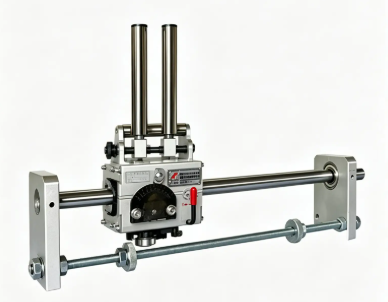
- 1Smooth rotating shaft
The upper horizontal shaft passes through the carriage.
- 2Moving carriage
The enclosed drive travels along the shaft and carries the guide.
- 3Stroke stops
Adjustable collars on the lower rod define the reversal region.
- 4Pipe-guide assembly
The upright guide elements direct material towards the reel.
2. See how the guide works with the coiler
On a pipe coiler, the traverse is part of a larger guiding and winding system. The reel takes up the pipe while the guide moves across the available coil width. Correct placement helps the next turn settle beside the preceding one instead of repeatedly winding at the same point.
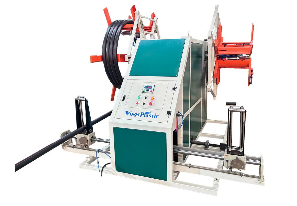
The Wings machine photo shows two guide and traverse assemblies in front of the winding stations. It gives the mechanism a physical context: guide height, pipe entry, travel space and access all need to fit the machine. The internal transmission and its ratio are not visible in this photo.
For a two-station machine, check each station individually. Its shaft rotation, reversing arrangement and intended starting direction must agree with the actual installation. A mirrored layout does not, by itself, tell you the required internal assembly orientation.
Two winding stations. Two guide assemblies.
3. How rotation becomes sideways travel
The inclined rolling contact is the key to the motion. Changing its setting changes the carriage’s axial advance for each shaft revolution. One inclination produces travel in one direction; the opposite inclination produces the return travel. A neutral setting can reduce the advance towards zero on models designed for that adjustment.
Think of the setting as an adjustable lead rather than a fixed screw thread. The useful number for setup is the carriage advance per shaft revolution, usually given in millimetres per revolution. Read that value from the manufacturer’s scale, calibration or specification for the actual unit.
The motion sketch highlights the relationship between contact inclination and axial travel. Use the installed unit’s calibrated lead scale for setup, rather than reading a setting angle from the drawing. Confirm the full adjustment range and the available thrust for the intended application.
Change the contact setting. Change travel direction.
Outward travel
Return travel
4. Match the traverse to reel rotation
Distinguish two quantities. Traverse lead is the axial travel per shaft revolution. Winding pitch is the axial spacing produced by one reel revolution. They are equal only when the relevant speed ratio makes them equal.
Let h be traverse lead in mm per shaft revolution, nₛ the shaft speed, and nᵣ the reel speed, both in rpm. Then traverse speed vₜ = h × nₛ, and winding pitch P = vₜ/nᵣ = h × (nₛ/nᵣ). With a fixed mechanical ratio and no slipping, the pitch stays constant as both speeds change together.
For example, assume a 12.5 mm traverse lead and a shaft rotating twice per reel revolution. The resulting winding pitch is 25 mm. At a reel speed of 10 rpm the traverse travels 250 mm/min; at 5 rpm it travels 125 mm/min. The pitch remains 25 mm in both cases. These are calculation examples, not recommended settings for a particular pipe.
An independently driven traverse also needs a matching speed reference or control strategy. Servo traverses can synchronise to reel rotation electronically; they do not universally require a separate coil-diameter sensor. Confirm how the proposed machine maintains pitch rather than judging it only by the type of drive.
| Reel speed | Shaft speed | Traverse speed | Winding pitch |
|---|---|---|---|
| 10 rpm | 20 rpm | 250 mm/min | 25 mm |
| 5 rpm | 10 rpm | 125 mm/min | 25 mm |
5. Set the pitch from the actual pipe
Begin with the measured pipe outside diameter and the intended winding pattern. The target is a stable layer in which neighbouring turns have the required spacing without forcing the pipe out of shape. Corrugations, ovality, temperature, guide position and winding pull can affect how the turns settle.
A pitch that is too small can force turns to climb over one another. A pitch that is too large leaves avoidable gaps and can let later turns fall between those below. The sketch shows these three outcomes using end-on pipe sections. It is a spacing comparison, not a cross-section of a particular coil.
Use the unit’s pitch control for adjustment within its rated range. If the required winding pitch falls outside that range, review the shaft-to-reel transmission ratio or the traverse size. Do not assume that a marked scale directly reads winding pitch; it may represent only the drive’s own advance.
Check the first turns at low speed, then observe several complete layers and both travel directions. Make a small change, record it and compare the result. A fixed clearance such as 0.2–0.5 mm is not a universal allowance for every pipe size or corrugated profile.
Too tight, correctly spaced or too wide?
Too tight
Turns can climb or overlap.
Matched spacing
A stable layer with the intended clearance.
Too wide
Gaps can leave later turns poorly supported.
6. Set the usable stroke and reversal points
The adjustable stops define where the reversing mechanism is actuated. The pipe landing position also depends on the guide offset, pipe bend and the movement that occurs during reversal. For that reason, the stop-to-stop distance is not automatically identical to the finished coil width.
Set the initial stops within the usable winding area, following the machine procedure. Secure the stops and check the carriage’s complete travel at low speed. Observe the actual pipe at each end: it should build the intended edge without climbing the reel boundary or repeatedly piling up.
If one edge builds higher than the other, compare the two stop settings, guide position and reversing action before changing pitch. Reversal behaviour can change with speed and lead setting. Verify the edge again when returning to the required production speed.
The real-machine details below show where guiding and traverse assemblies sit in the pipe path. Use the relevant mechanism’s drawing to identify its exact stop and adjustment screws; the photograph alone is not an instruction to loosen an unidentified fastener.
Look at the guide, carriage and available travel.
Two enlarged regions from the same machine photo above.
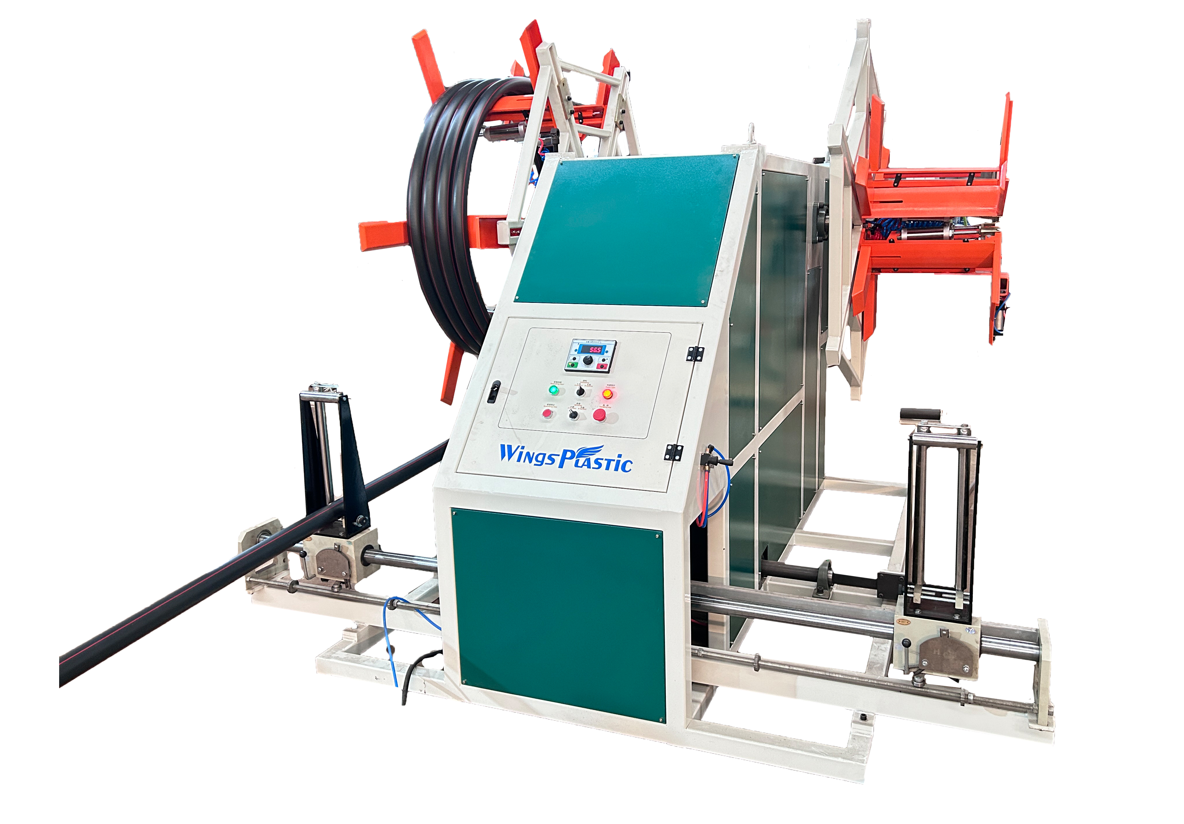
Follow the incoming pipe through the guide to see how its position relates to the reel.
Check the carriage, guide clearance and travel space against the installed mechanism’s drawing.
- Confirm the usable winding width and pipe landing points.
- Set and lock both stroke stops.
- Check travel and reversal at low speed using the machine’s approved procedure.
- Inspect both coil edges at the intended operating speed.
7. Diagnose the symptom before changing pressure
Record when the problem appears: throughout the stroke, only at an end, only at a certain shaft position or during a reel-speed change. That distinction helps separate pitch setup, reversing trouble, alignment and winding-speed disturbances.
Do not use greater contact pressure as the first response to every slipping complaint. Excess load, incorrect lubricant, worn parts, installation errors or a mismatched operating direction may need a different remedy. Pressure and thrust settings belong to the specific model’s procedure.
Also watch the reel and pipe loop. A traverse can move correctly while changing winding pull makes the pipe land badly. If the fault follows repeated reel starts and stops, review winding-speed and traverse coordination before disturbing a correctly set carriage.
| Symptom | Check first | Next step |
|---|---|---|
| Pitch varies during travel | Speed ratio, slipping, shaft condition and guide resistance | Identify the disturbance; confirm the unit’s load and adjustment limits. |
| Pipe piles up at an edge | Stop security, guide position and reversing action | Correct the affected end, then recheck at production speed. |
| Carriage sticks or moves unevenly | Alignment, contamination, damaged shaft and rolling-element condition | Isolate the equipment and inspect using the model instructions. |
| Wrong starting direction or failed reversal | Specified shaft rotation and installed reversing configuration | Compare the installed unit with its order and assembly instructions. |
| Uneven lay during speed changes | Reel acceleration, pipe reserve and traverse synchronisation | Review the winding control sequence as a complete system. |
8. Maintain the unit and verify its direction
Keep the shaft, guides and reversing parts in the condition required by the manufacturer. Identify the specified lubricant and application method for the fitted model. Lubrication requirements differ; a universal instruction to keep every shaft dry, oily or coated with dry-film lubricant is not appropriate.
Inspect stop security, contact surfaces, guide freedom and signs of wear. Use the manufacturer’s inspection criteria rather than applying a universal roller-wear limit or spring-length percentage. Any new noise, heat or sticking should be investigated before it damages the shaft or carriage.
Shaft rotation and reversal configuration need particular attention when replacing a traverse. Record the viewing end for clockwise or counter-clockwise rotation, required first travel direction, model marking and reversing arrangement. Do not rely on an unexplained “left” or “right” label.
Some units require specific switching-mechanism changes for another shaft rotation. Turning an internal assembly through 180 degrees is not a universal conversion procedure. Get the correct model instructions or replacement unit instead of copying a generic internal-flip diagram. Carry out inspection and adjustment under the machine’s isolation and access procedures.
Reference: Uhing rolling-ring drive operating instructions. A manufacturer reference for rolling-ring operation. Match maintenance and direction changes to the instructions for your installed unit.
9. Choose a traverse for the complete winding task
A rolling-ring traverse can offer adjustable lead and mechanical reciprocation in a compact arrangement. A lead-screw or servo traverse may be appropriate for other load, precision or automation requirements. Compare the actual guide load, stroke, lead range, reversal behaviour and maintenance access.
When requesting a coiler or replacement traverse, provide the pipe size and profile, required winding width and pitch, reel-speed range, shaft diameter and rotation, guide load and station layout. A clear photo of the existing mechanism and its marking is particularly useful.
For a new machine, define the traverse together with coil dimensions and winding control. Neat turns, suitable pipe bending and manageable winding pull must work together. A well-adjusted traverse cannot correct an unsuitable core diameter or an unstable take-up speed.